ESP variable speed drives provide embedded automation and high efficiency operation with precision control of all traditional and PM motor designs.
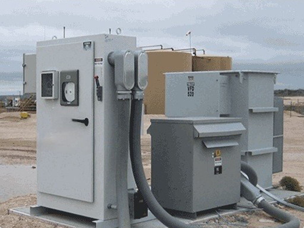
ESP variable speed drives provide embedded automation and high efficiency operation with precision control of all traditional and PM motor designs. They feature low harmonics and unrivaled motor protection from 10 to 1200 hp.
Advanced drive features include power disturbance ride-thru, backspin sensing, closed-loop speed and torque regulation, gas-lock mitigation, stuck pump mitigation, and sensor-less fluid level estimate / control.
Patented AHD™ technology actively reduces input harmonic distortion. A Quick-Start screen provides simple, guided start-up including on-the-fly pump direction identification and reversal. Embedded modeling of transformer, drive, cable, motor, and pump ensures proper setup and performance.
Purpose-built drive technology engineered for maximum production, protection, and efficiency in ESP applications.
At any instant during the life of a well, there is a single constraint that limits production. Production can be maximized without compromising efficiency or reliability by forcing the system to operate at the constraint limiting production at each instant of time.
Models of all the system elements are run in real-time at the wellhead to detect appropriate limits and enforce associated control strategies. At different points in time, the system may be limited by motor voltage, motor current, motor speed, motor torque, motor thermal capacity, power demand, rod string torque, flow line pressure, fluid level, or well inflow.
Embedded mathematical models of the drive, motor, drive head, rod string, pump, flow line, tubing, casing, fluid, and reservoir use component specifications and well completion information along with field setup parameters to monitor pumping system operation.
Identification routines automatically determine installation-dependent system parameters including those of the motor, rod string, and pump. The models capture the thermal, mechanical, electrical, and hydraulic behavior of the system to control the pumping process with greater precision than ever before.
The drive uses a number of unique methods for precisely determining performance parameters from models of the pumping system elements without requiring external surface or downhole sensors.
Sensorless system variables including rod speed, rod torque, pump speed, pump torque, fluid flow, fluid level, suction pressure, discharge pressure, and differential pressure can be observed through the drive keypad/display or recorded as circle charts and time-based plots. Fluid level, pump flow, and total production are displayed in selectable engineering units.
The drive provides a number of options for manual, remote, and automatic control of pump speed. Speed commands can be selected from a number of sources including potentiometer adjustments, keypad presets, serial data communications, and internal optimization controllers.
The motor can be operated up to twice base speed at constant power. This allows the overall gear ratio to be increased, thereby providing increased low-speed torque without loss of maximum pump speed. Dual motors can be controlled from a single drive for the operation of large pumps.
Level control maximizes fluid production by regulating the downhole pump inlet pressure. An optional surface flow sensor can be used to automatically locate the point of maximum production while protecting the system from a pump-off condition.
A search routine uses an optional gas flow sensor input to automatically select the fluid level that maximizes gas production in coalbed methane pumping applications. Current limit control increases production by raising motor speed during periods of reduced pump load.
Pump-off control maximizes well production for any given inflow characteristic. Fluid level over the pump intake is precisely controlled by differential sensing of casing gas and pump intake pressure.
A pump-off control allows the pump to dwell for a programmable period of time to protect the pump and to control average flow. A dwell period minimum pump speed can be used to prevent sanding in the well.
A power flow optimizer reduces the electric utility cost for any inflow rate. A cyclic energy optimizer provides additional utility cost reduction by pumping at the maximum efficiency point necessary to achieve the required flow.
Time of use control can be used to minimize on-peak energy demand charges. The drive incorporates an input power meter as well as displays of input power, motor power, pump power, and average efficiency to aid in utility cost control.
A pump flow monitor provides a continuous estimate of flow without the need for additional instrumentation. Pumping speed and pump effective volume are used to estimate the actual production rate.
Pump flow is totaled in a resettable production accumulator. Estimated well production is displayed for the operator and is available for remote well monitoring through a serial communication port.
A fluid level monitor provides a continuous estimate of level from pump head, fluid properties, tubing pressure, and casing pressure. Tubing and casing pressures can be entered as parameters for relatively fixed pressures or input from analog sensors for significantly variable pressures.
Torque limiting protects the motor from excessive torque loads and the rod string against breakage. Stick-slip oscillation damping reduced rod string fatigue failures. Excess flow line pressure can be used to prevent damaging pump loads.
Low-speed detection protects the system in case of a stall condition, such as a stuck pump or blocked flow line. Breakaway torque detection identifies pump problems during starting. Low torque detection indicates a rod break, belt failure, or plugged sand screen. Sensing of pump inlet and outlet differential pressure is used to protect the pump from overloading.
The drive can automatically recover from fault conditions and intermittent power outages to ensure continuous operation of unattended wells. Auto-restart control sequences starting of multiple pumps after power outages to eliminate surges in power demand. Start/stop events are automatically logged for subsequent retrieval.
A data sampler option captures real-time information for the generation of motor, rod, and pump performance charts as well as plots of production information. A data logger collects time-stamped fault, warning, and event logs that can be viewed through the drive keypad/display, uploaded to a personal computer, or retrieved by a network server.
Typical events include start, stop mode change, power up, power loss, overvoltage, overcurrent, low torque, and low speed. A multichannel analog interface option allows data logging of additional well parameters.
Several industry-standard serial protocols are available for communicating with popular programmable controllers as well as personal computers or network servers. Available protocols include Modbus RTU, Modbus Plus, ControlNet, Profibus, and Ethernet.
Optional software is available for monitoring the pumping system using an iPhone or iPad handheld device, Windows-based personal computer, or network server. A wireless interface option allows remote monitoring of system performance and control of pump operation. User-programmable reports can be generated using software that connects system parameters to Excel spreadsheets.
Talk to our engineers about ESP Drives and Control for your wells.
We are proud to partner with some of the most respected names in oil and gas production and exploration.